Precision Lead Screw Assemblies
Accuracies to 10 microinches per turn, 25 microinches per inch
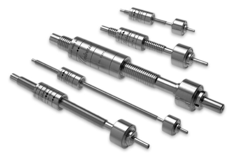
Universal's high-quality lead screw assemblies meet your most demanding micro positioning applications. Specify lead accuracies of 10 microinches per turn and 25 microinches per inch, the best in the industry!
Unmatched lead accuracies minimize thread helix nonlinearity, eliminating the "once around" banding problems common in high-performance graphic imaging equipment such as color scanners, recorders, and printers. Other application examples include photomask inspection, semiconductor manufacturing and prepress imaging.
Accuracy:
- Standard: 0.000050"/turn, 0.000100"/inch
- Available: 0.000010"/turn, 0.000025"/inch
Stock Sizes:
- 1/4" diameter, travel to 8"
- 1/2" diameter, travel to 20"
Standard Leads:
- Commonly used leads from 0.025" to 0.400", 1 mm to 5 mm.
Universal’s precision components are factory assembled, preloaded, and "run in" under ideal conditions. The patented self-aligning* and self-adjusting* nut and thrust bushing will accommodate and reduce the effects of misalignment and slide errors to bring out the best in stepping motor or servo systems.
With many built-in features, Universal lead screws offer designers distinct advantages compared to ball bearing screws and conventional lead screws. Key features include:
- Smoothness of operation
- No noise
- Absolute, repeatable positioning accuracy over a distance
- Self-aligning nut eliminates side loading of linear bearings and prevents nut binding or positioning error due to misalignment in lead screw installation
- Self-compensation for pitch diameter variation extends life expectancy without performance degradation
- Minimum helical nonlinearity within a revolution (drunkenness); important for equal step size or constant velocity applications
- Anti-backlash nut design for bidirectional repeatability
* U.S. Patent Numbers: 3,977,269; 3,831,460; 4,434,677